Reading The ‘83/’84 Wiring Diagrams (“For Dummies”) by RJTW
________________________________________
I haven’t seen many threads on the topic of how to read the Porsche wiring
diagrams, and none on my particular model year (1983) which I understand uses a
different format from the later diagrams. I recently tracked down some
electrical gremlins and spent some quality time with these diagrams. It turns
out that the ’83 version is not available online, but the ’84 is, and the cars
are virtually identical.
I thought I’d start this thread to share the basics on how to read the ‘83/’84
diagrams for anyone else interested. While everything I share below is in that
context, perhaps at least some of this will apply to other years as well. And
feel free to jump in, add notes, corrections, and comments for this and for any
other year. I by no means represent that this is a full or complete tutorial,
but it will be enough to get you most of the way there.
I’d really like to thank Dr. Bob for both leading me through the wiring diagrams
in a recent thread, and also for reviewing the contents of this post for
technical accuracy – thanks Dr. Bob!!
SOURCES
First off, there are two different wiring diagrams made by Porsche for '83/’84
that go hand-in-hand: the “wiring diagram” and the “current flow diagram.” I
picked up the wiring diagram at ligeti (
http://www.ligeti.com/928/
) and the current flow diagram from manualslib (
https://www.manualslib.com/brand/porsche/automobile.html ). There may
be other online sources too. I believe that Roger and possibly other vendors
also have this information, and complete workshop manuals, available on CD.
Not every manual for every year is shown on the above websites, and it appears
the “current flow diagram” is only available at the above source for years
1980-1983. Later years, at least after ’84, appear to have done away with this
document. I’ll explain it anyway, using the 1983 version, after the wiring
diagram.
I should also mention that a much more extensive dive into 928 diagrams with a
focus on the ’87-94 by Alan Moore is available here:
http://928-electrics.com/wiring%20diagram%20primers.htm
Also, for reference, here is Alan's thread with single-page central electric
panel diagrams (fuse, relay, and lettered plug locations) for all years (keep
scrolling down until you find your model year):
https://rennlist.com/forums/928-forum/799140-updated-single-page-central-electric-panel-relay-fuse-and-plug-details-all-years.html
For my purposes, I am going divide up the wiring diagrams into THREE parts
for ease of understanding:
1) The central electrical panel diagram, labeled “Central Electric,” at the
beginning of the wiring diagram document. This is a one-pager that shows an
abstract representation of all inputs to, outputs from, and interconnections
inside of the central electric panel via tiny numbers and letters which seem
like a secret indecipherable code at first. It also shows all fuses, all relays,
and all the lettered/colored plugs attached to the central panel. Because so
much depends on this one diagram, I break it out separately.
2) The rest of the wiring diagram document, which shows the connections in the
rest of the car and how they are connected with each other and to the central
panel.
3) And finally, the current flow diagram which repeats much of the same
information but, importantly, gives us information about specific wire colors,
ground point locations, and connector locations. The current flow diagram –
unlike the wiring diagram, which is largely divided by location in the car and
not function -- is also helpfully divided into specific circuits/functions (such
as fuel injection, ignition, etc.) that focus only on those areas.
To reiterate, everything I say below is specific to the MY'83/’84 diagrams.
The central electrical panel diagram is reproduced below:
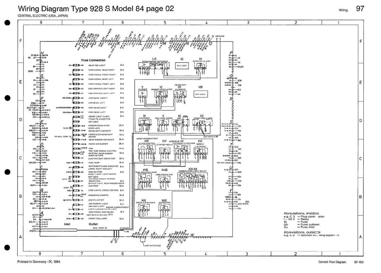
This diagram is fantastic: It shows in a very compact form all the fuses and
relays of the central panel PLUS all of the inputs and outputs of the panel (the
colored/lettered connectors at the bottom of the physical panel). It also shows
what all the mess of wires behind the panel is actually doing (that is, all the
interconnects within the panel itself between the connectors, fuses, and
relays).
What makes this interesting is that it doesn’t actually show most of the lines
representing the physical interconnects, but instead relies on a pretty simple
and clever kind of numbering system. I’ll call them “references.” That system is
the key to understanding this page, and the rest of the wiring diagram. It
actually ends up being more simple and less cluttered than if they had actually
attempted to draw all the dozens of physical interconnects on the panel.
So let’s get right into it. Here’s how to read the diagram:
Let’s work from the inside out. First, the fuses are shown stacked up vertically
on the middle left (along with their names and amp ratings), and all the relays
to the right.
Next, find the first box drawn around the fuses and relays. It has the letters A
through Z going around the outside, along with a bunch of little notations. Each
letter A through Z corresponds to a colored and correspondingly lettered plug at
the base of the physical panel in the car (though some letters/plugs are
nonexistent in the car and on the diagram for some reason, like the letter “I”).
Likewise, each of the notations for each of the lettered connectors is a
reference to tell you exactly where each pin in that connector leads. The pins
are numbered in the diagram along the perimeter of the box for each lettered
connector, usually from 1 to 8, but it varies depending on the actual number of
pins in the physical connector. By the way, if you pull any of the connectors on
the actual panel, you can see the pin numbers molded into the connector itself.
Also note that the entire page itself is framed by a larger box that forms a
letter/number cross-reference grid like a map. In fact, every other page in the
wiring diagram contains the same type of grid, and you’ll be using it to find
particular references.
The key to understanding this chart (and what had me really confused for a
while) is that there are TWO reference systems going on in this chart. German
over-engineering at work, no doubt!
Every reference on the OUTSIDE of the box refers to a grid section in some later
page of the wiring diagram document. You’ll need to scroll down through the
various pages until you run across the corresponding “map grid” reference, which
is kind of like finding the right block on a street but not the right house. As
an example, let’s say you’re looking at connector T, pin 1, and on the outside
of the box see a reference to “G22”. See below.
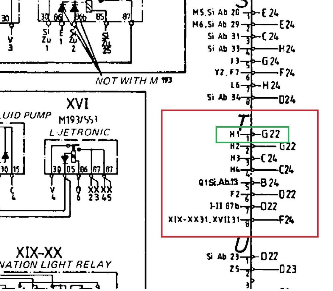
You’d then start scrolling down in the document, looking at the outside grid
box on each page. (You’ll notice that the letters across the top generally stay
the same on every page, but the numbers running down the side generally
increase). Grid reference G22 lives on what the document calls “page 4”, titled
“Passenger Compartment and Rear End.” Within grid G22, just like on a map, there
may be multiple electrical connections going on and you’ll need to pinpoint the
exact one originating from connector T pin 1. Here’s the area around G-22:
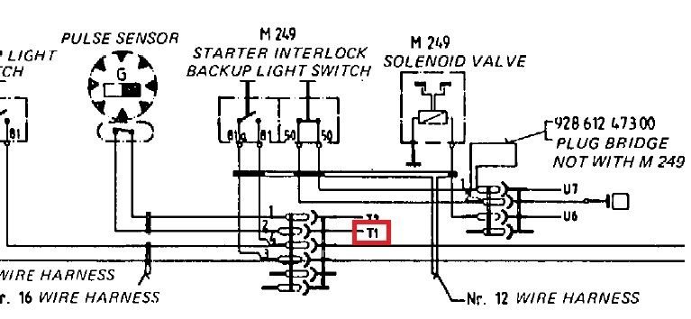 Finding
the exact termination from connector T pin 1 is easy – it’s labeled as “T1”. It
is connected via a 6-pin connector to the pulse sensor (and although this
diagram doesn’t show it, you might happen to know that the pulse sensor is
located in the differential area – more about locating components later). So now
you know exactly where that pin’s wire leads to!
Finding
the exact termination from connector T pin 1 is easy – it’s labeled as “T1”. It
is connected via a 6-pin connector to the pulse sensor (and although this
diagram doesn’t show it, you might happen to know that the pulse sensor is
located in the differential area – more about locating components later). So now
you know exactly where that pin’s wire leads to!
For every reference INSIDE the box, even though some of them have the exact same
format (a capital letter followed by a number), this is now always a reference
to something else inside this SAME box, within the central panel. However, the
references now come in multiple forms. Here they are:
- A letter followed by a number (like “T1”): refers to a lettered connector and
pin number. This is the case when one pin in a connector is directly connected
to a second pin (usually in a different connector). So, for instance, we can see
in the previous picture for connector T that pin 1 is labeled “H1” on the inside
of the box. That means that T1 is connected over to connector H, pin 1, inside
the central electrical panel. Likewise, connector H, pin 1, has a reference “T1”
on the inside of the box to refer to the same connection back to T1.
- A Roman numeral followed by a number (like “XIV 85”): refers to the
corresponding numbered relay and terminal number. This means the pin in question
connects to a relay. For instance, a reference “XIV 85” means that the pin
connects to relay XIV, Terminal 85. For another example, refer back to the
picture above of connector T. Its pin 8 has this reference: “XIX-XX 31, XVII
31”. This means that pin 8 connects to both Terminal 31 of the combination relay
XIX-XX (the lighting relay) and to Terminal 31 of relay XVII (the fuel pump
relay).
- “Si. Zu.” or “Si. Ab.” followed by a number: refers to a fuse number. “Si. Zu.”
refers to the fuse input, “Si. Ab.” refers to the fuse output. Going back to
connector T again, we see that its pin 5 has this reference: “Q1 Si. Ab. 13”.
This is another example of a shared connection – the pin connects both to
connector Q pin 1, and also to the output of fuse 13 (which we can see on the
page is labeled as the fuel pump relay). (By the way, the output side of T5 is
labeled “B22”… that’s a reference “outside” the box and thus to the map grid…
and if we look that up on the grid, we can see that T5 connects to the fuel pump
– as expected!)
Oh, and by the way, you’ll also see that SOME wiring connections are actually
drawn in as lines, as you’d normally expect. Most of these lines are related to
the basic 12V connections from the battery to various relays and some of the
inter-relay connections.
While there’s some other stuff happening on these diagrams, it’s all pretty
self-explanatory (such as wiring harnesses and connectors). But one other thing
I’ll mention is that certain numbers keep popping up, and they have standard
meanings that ultimately derive from our DIN standard-based Bosch electronics.
For instance, Terminal Circuit 30 is an always-on 12V “rail”. Terminal 50
engages the starter. There are standard DIN circuit numbers that sometimes share
a designation on a device like a relay. The standard DIN circuits we look at in
the 928 include circuit 30, which is unfused battery voltage and always has the
standard red wire color. Circuit 31 is always chassis ground, and has a standard
brown wire color. As mentioned, circuit 50 is always the trigger to the starter
solenoid, and is always yellow. Circuit 15 is on when the ignition switch is in
position II (engine run) or position III (Start). There are non-DIN standards
including a circuit X, which is on when the ignition switch is in position II
(run) only. Circuit X includes a circuit that’s connected to terminal X on the
ignition switch, but may also include a circuit that’s through a relay triggered
by the ignition switch contact X, or may be a relay that has a coil bridging the
15 and 50 contacts on the ignition switch to provide the same function. There
are more standard circuits too (see “References” below). As you work through the
diagrams you’ll see how it all works.
The Current Flow Diagram
The good news on the current flow diagram is that it provides several more
pieces of information in addition to the wiring diagram to help give us the
complete picture. First, it breaks down the electrical system into specific
inter-related operational subsystems, like the starter/ignition/fuel pump, the
ignition switch, and so on, so that it’s often much easier to understand and
trace each specific system. This is in contrast to the wiring diagram which is
based more on physical location (e.g. front end, passenger compartment, etc.
where all systems are intertwined). In addition, it provides a couple of pieces
of critical information that are mostly or completely absent from the wiring
diagram: the actual wire sizes and colors, and the physical location and type of
the various wiring loom connectors. This is great if you're trying to trace down
where a particular wire runs -- you'll not only be able to find out what it
looks like, but what connectors it runs through, and even if the wire changes
colors along the way.
The bad news on the current flow diagram is that it uses its own, different
system of references totally different than the wiring diagrams. Having said
that, it DOES refer to the same terminal numbers as the wiring diagram.
As such, you'll sometimes need to refer to BOTH the wiring diagram AND the
current flow diagram to fully understand any given circuit, both in the
conceptual sense of how it works and also how it is implemented in the actual
car.
There is a lot happening in the current flow diagram, and to be honest,
everything you need to know is on the second page of the document where there is
a legend that specifies what all the symbols mean.
However, let's work through an example. I'm using the '83 version of the current
flow diagram I found online.
EXAMPLE
I recently worked on diagnosing an intermittent no-start condition on my ’83. I
knew from other tests that one possible culprit was an intermittent or high
resistance ground from the starter relay, number XIV. Let’s trace that out in
the current flow diagram, on “Part I”, which covers “Power Supply, Starter”,
“Ignition”, and “Fuel Pump”:
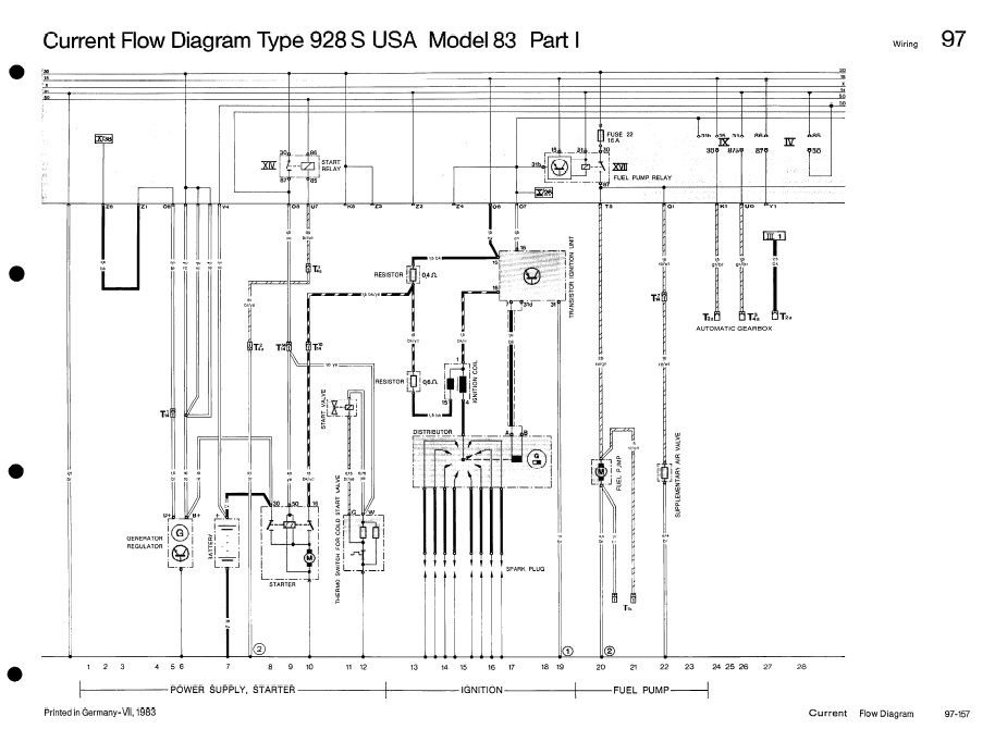
Find the starter relay, which is relay XIV. Here’s a close up picture from
the above figure with the relay outlined:
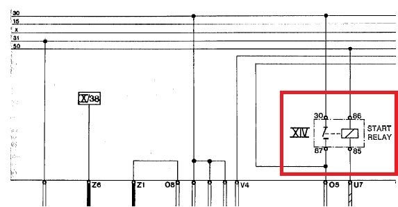
There is a lot of useful information here:
- Pin 85 goes towards ground (shown on the figure, but cut out above).
- Pin 86 starts the process when circuit 50, the horizontal line depicted
above the relay, is energized. This is a case where we need the wiring
diagram to tell us what circuit 50 does. We can look this up back on the
wiring diagram and work backwards to see that pin 86 is connected out
through connector A pin 6… which goes to the ignition switch… which in turn
is energized from a line from connector A pin 2… which in turn is connected
to rail 30, which is always 12V. We can also see that there is a terminal 50
labeled on the ignition switch in the wiring diagram. So, circuit 50 (coming
into the relay via its terminal 86) is +12V when the key is turned to the
“start” position. This will energize the relay and close the contacts from
terminals 30 to 87.
- Terminal 30 is connected to rail 30, always +12V (we know this from the
wiring diagram).
- Terminal 87 is what actually leads to the starter’s terminal 50 (again
shown in the diagram but clipped above) – in fact, it’s the famous yellow
line in the 14-pin terminal under the hood – but I’m getting ahead of
myself!
- We can also see that Terminal 87 leaves the central electric panel via
Connector O, pin 5, and that the ground line Terminal 85 leaves via
Connector U, pin 7.
OK, so let’s start debugging! Where does line 50, the starter line, go, and
where does that pesky ground line go? Let's look further down in the same
diagram and see:
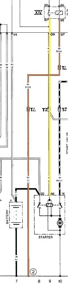
By convention, the bottom rail on the diagram is chassis ground.
So, we can see that pin 87 goes out through Connector O pin 5 as above, goes
through a box labeled “T1414”, and is connected to Terminal 50 at the starter.
I've colored it in yellow, above.
The box labeled “T1414” is explained back on the legend page at the front of the
document. The subscript, 14, means it's a 14-pin connector. The superscript,
here by coincidence also 14, refers to the pin number within that connector. And
finally, the legend page ALSO tells us the location of every connector in the
document (and hopefully in the car): there is only one such connector, "in
engine compartment, right." The famous 14-pin connector by the jump post!
OK, let’s trace out the ground wire leading from pin 85 which I’ve colored in
brown, it’s a little more interesting: It first goes through a brown and yellow
line from Connector U pin 7, to a connector labeled “T41a”, then to a second
connector labeled “T42a” where, by the way, it switches color to plain brown. It
then grounds out at a location labeled "2" (the number 2 being inside a circle
-- explained below).
What is “T41a” and “T42a”? Looking back at the legend again, we see this is a
4-pin connector, referring to pins 1 and 2, and it's labeled as connector "a".
(Unlike the 14-pin connector where there is only one such connector, here there
are multiple 4-pin connectors and Porsche gives each its own lower-case letter).
So, we have established that the ground actually goes through the same
connector, out through pin 1 and back through pin 2 -- a loopback, we can
deduce. And finally, the legend tells us that the 4-pin connector "a" is located
"in spare wheel well."
After going back through pin 2, the wire changes colors to plain brown and goes
to ground point 2 (in a circle). Again, the legend has a location for every
numbered ground point -- here, it is "at rear of wheel arch underneath right
rear trim panel."
So there we have it – wires, locations, and an understandable circuit diagram.
And, in conjunction with the wiring diagram, we can literally trace the entire
electron flow from the battery to ground. In my case, understanding that the
ground point for the start relay is actually located in the REAR of the car, I
was able to start focusing on locating/cleaning that ground AND the associated
4-pin loopback connector that the ground passes through.
Note that the referenced circuit and flow path is specific to 5-speed cars,
where the jumper/loopback shown between T41a and T42a actually passes through a
switch on the automatic gearbox (on the auto cars) that's often referred to as
the "neutral safety switch." That switch closes the loop from the relay to that
rear ground point only when the gear selector is in the Neutral or Park
position.
References between Sheets in the Current Flow Diagram
That just about wraps it up on the current flow diagram, but there’s one more
thing to mention. And, of course, it involves yet ANOTHER system of references –
and also of course, it’s a different reference system than on the wiring
diagram!!
Every once in a while you’ll see something like this: A circuit which seems to
suddenly stop, labeled with a Roman numeral. This is an example from Sheet 1:
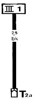
This may seem like a reference to a relay, but it’s not. (Relays are also
shown with Roman numerals, but they’re always depicted as a relay). Instead,
this is how Porsche ties together multiple pages in the current flow diagram.
Most of the time, each page in the current flow diagram is largely if not
entirely self-contained. But sometimes, there are connections to other systems
or circuits depicted on separate currently flow sheets, and that’s where this
system comes in.
The reference refers to Sheet III (in the current flow diagram document),
“track” 1. “Tracks” are the small numerals displayed across the bottom of every
sheet. Frankly, most of the time I think they can be ignored, except for this
one use case. Here, the above picture is shown on Sheet I, and it’s in track 27.
(I guess this is why almost all the wires in the circuits are displayed as
vertical lines). If you flip to Sheet III and start looking around in Track 1,
you’ll eventually find a reference to “I 27” – that is, Sheet I, track 27.
That’s a match! And it means that it’s the same line crossing through from one
sheet to another.
Other Information Resources
Below, I’ve attached copies of both the wiring diagram and the circuit flow
diagram. Plus, I’ve attached a couple of other general resources which may be
helpful. The first is an article entitled “Understanding European DIN Wiring”
from 2003, which explains the underlying automotive standards (and also walks us
through common European wiring diagram conventions). The second is a table of
terminal designations according to DIN 72552, which details the many
standardized terminal and circuit designations used on European cars (such as
the designation of the starter circuit as “50”).
EDIT: I'm also adding in the "928S Electrical Troubleshooting & Repair" document
which I received from Wayne Strutt (thanks Wayne!!) This document is packed with
information: The DIN terminal numbers used in our cars (again); an overview of
the ground locations; the central electrical panel layouts 80-85; and
information about the central warning system. Cool stuff! Wayne also sent me a
PDF of the "Electric 928 Training" manual which has some very detailed
information on the operation of most (all?) of the electrical subsystems on the
car (and, amazingly, a how-to tutorial on reading the wiring diagrams! LOL!)
Unfortunately it's 13MB and it exceeds the 5MB limit on attachments here, but PM
me with your email address if interested and we can see if that works.
Also, here is a link to Alan Moore's updated single-page central electric panel
diagrams:
https://rennlist.com/forums/928-forum/799140-updated-single-page-central-electric-panel-relay-fuse-and-plug-details-all-years.html
And Alan's primer on reading the later wiring diagrams, linked above:
http://928-electrics.com/wiring%20diagram%20primers.htm
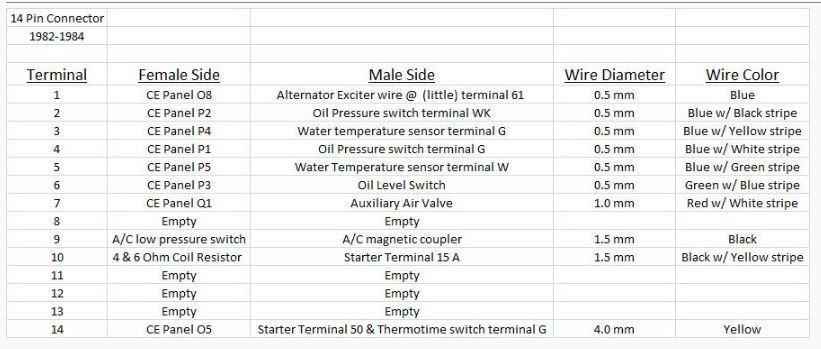
And finally, Wayne Strutt also provided the pin assignments on the 14-pin
connector by the hot post:
That sums up my initial set of posts. I hope this is helpful!
Porsche 928 Wiring
Diagram - 1984.pdf
928_usa__1983_current_flow_diagram.pdf
928S
Electrical Troubleshooting & Repair 80-85.pdf
klemmenbezeichnungen.pdf
Example: Debugging a No-Start, No-Crank Problem
As an example of how to use the wiring diagrams in action, let's use them to run
through a very typical scenario. Let’s say your ‘83/’84 US car doesn’t crank,
meaning that the starter and solenoid don’t move at all when you turn the key.
Here are the steps to follow to isolate the cause. With some minor differences
with relays and pin locations, the general procedure applies to other years.
Before you start, the regular advice always holds. First, ensure that your
battery is fully charged. From Dr. Bob: “Check the battery condition. My annual
maintenance protocol includes sampling the electrolyte for specific gravity. A
cheap (~$3) tester from Wal-Mart or your parts store is fine. It has an
eye-dropper with colored balls inside. Each ball is a different density, so a
low specific gravity of fluid in the tube may not float the heavier balls. The
colors give you an idea of cell condition based on the heaviest ball still
floating when you draw a sample from a cell. If any sample has a green ball
falling, you are casually comparing battery price and availability. When any
yellow balls are sinking, you are seriously shopping. If any red balls start
falling, immediately take a car other than the 928 to the battery store. The
specific gravity test offers you a little warning before you get stranded. The
test must be done with a fully-charged battery, and the battery must be allowed
to stabilize for at least 30 mins after charging ceases.”
Second, have you cleaned ALL your grounds and checked your battery ground strap
and engine ground strap? See the “New Visitor” thread for information on how to
do that. I’ll also share some advice at the end about the importance of cleaning
contacts and using DeOxit any time you’re working on the electrical system.
Third, have you replaced or swapped your starter relay, XIV? Replace it with a
spare, or try swapping the starter relay with the horn relay (X). By the way,
it’s a good idea to always have a new, spare starter relay and fuel injection
relay. Try starting the engine again and see if that works.
Fourth, remove the top cover of the 14-pin connector by the hot post. (Don’t
actually pull the connector apart because the little connectors can simply fall
out of the plastic housing). Pin 14 in the connector will be a yellow wire. You
can do a hack test on the starter here: Turn the key to the “run” position, and
make sure you’re in neutral or park, your parking brake is set, and that it’s
safe to start the engine. Using some alligator clips or a wire, touch one end of
the wire to the hot post, and very carefully touch the other end to the yellow
pin for a moment. If the starter engages and starts the engine, that’s great
news, as it means the yellow wire leading from there down to the starter (via
the front-of-engine harness) – and the starter itself – are OK. If this test
does not crank the starter, then you either have bad connectivity in the engine
front harness, or there’s a starter problem. If you suspect a continuity issue,
then carefully unplug the 14-pin connector, making sure that the pins stay in,
and use an ohm meter to test continuity between the yellow pin there and the
yellow wire at the starter itself. This tests continuity of the yellow wire in
the front-of-engine harness. If continuity appears good, you may have a bad
starter.
The next series of posts will focus on ensuring you receive a 12V signal at the
yellow pin when the key is turned to Start.
Overview and Typical Fault Areas
As an overview, here’s how the system is supposed to work: when the ignition
key is moved to the “start” position, the ignition switch connects 12v to the
starter relay (a very low current draw). The starter relay then engages,
bridging its internal contacts to connect 12v to a wire (the “yellow wire”)
which is capable of carrying the current draw of the solenoid. This energizes
the solenoid, moving the starter to engage the teeth of the flywheel ring. The
starter itself then draws current directly from the battery positive cable to
crank the engine.
Possible, or at least common, failures include: a faulty ignition switch (which
doesn’t send 12V to the starter relay); a faulty ground on the low current side
of the starter relay so that the relay never engages (possibly caused by a bad
ground or a dirty connector in the path to ground, and on automatic cars,
possibly a bad transmission interlock switch which lifts ground to prevent
starting except when the gear selector is in P or N), a faulty XIV starter
relay, dirty connectors to or from the central panel, a dirty 14-pin connector
near the jump post under the hood (the yellow wire passes through here on the
way to the starter), or faulty wiring in the harnesses between the central panel
and the starter. The below tutorial should be able to help you isolate any one
of these causes.
Understanding the Start Circuit in Detail
Let’s follow the current path, starting with the connections around the ignition
switch and central panel.
Turning the key causes a 12V connection to be made to the starter relay. Let’s
look into what’s going on there. Here is a close up from the wiring diagram,
page 2 (central panel):
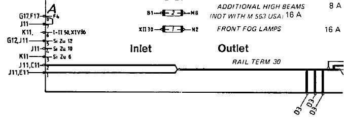
Unswitched battery voltage arrives at the central panel through three
connectors, seen at the lower right of the diagram. Those connectors are, on
earlier cars, three individual red wires which plug into the central panel in
the middle of the board, in between connectors “N” and “O”. I believe later cars
have a different connection point. For what it’s worth, battery voltage travels
from the battery, through the battery cable underneath the car, to the starter.
At the starter, the battery cable meets the front-of-engine harness, and from
there to the alternator and to the hot post under the hood near the 14-pin
connector. This is the large red wire that feeds the hot post. At the hot post,
the large red wire is connected to three smaller red wires, which travel through
the main underhood harness back to the central panel forming the above three
connections.
The three unfused connections together form “Rail Term 30,” an always-on 12V
circuit. Rail Term 30 is connected inside the central panel to connector A, pins
1 and 2 (we see that over on the left). Those pins lead out to grid references
J11, C11, and E11. For our purposes, we only need to focus on grid reference J11
– the ignition switch:
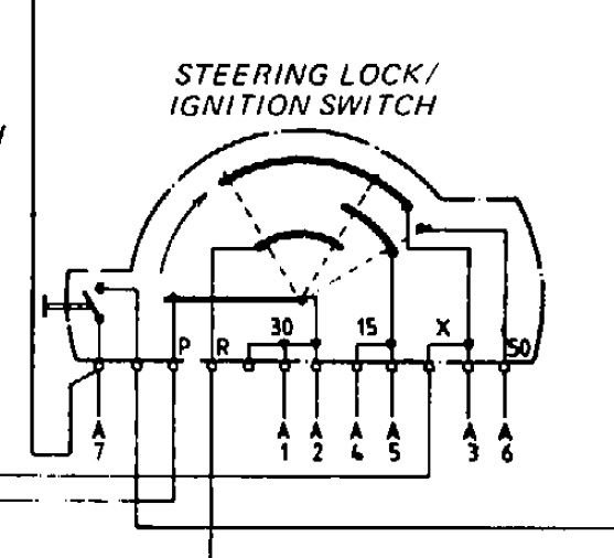
When the key is turned to the “Start” position, we can see that the wires
from connector pins A1 and A2 get connected to connector pin A6, and is labeled
“50”. As discussed previously, this is the starter circuit.
So, electricity goes from the battery, to the central panel, out connector A
pins 1 and 2 to the ignition switch, and back to the central panel via pin A6.
If we go back up to the closeup of the central panel, above, we can see that pin
A6 is connected to “I-II 50, XIV 86”. Because we’re focusing on the starting
system, we can ignore relay I-II (the rear defrost relay) and look only at XIV
(the start relay). So, turning the key energizes the start relay, terminal 86.
Let’s take a look at the start relay again:

12V comes in to terminal 86 from the ignition switch (via A6), and current
flows through the coil in the relay and to ground through terminal 85. The
ground wire leaves the central panel through connector U, pin 7. As we saw in an
earlier post in this thread, we used the current flow diagram to determine that
the ground itself is located under the right rear quarter panel, and on its way
there goes through a connector in the spare wheel well and, for auto cars, the
transmission interlock switch.
Likewise, when the ignition switch energizes terminal 86 and current is allowed
to flow to ground, then terminal 87 is bridged by the relay to terminal 30 (the
always-on circuit). Terminal 87 is the “yellow wire” destined for the starter.
The wire leaves the central panel via Connector O pin 5, and we already know
that it travels in the main engine harness to Pin 14 of the 14-pin connector by
the hot post, and from there through the front-of-engine harness to the starter.
By the way, the debug procedure outlined below will work on virtually any year
928, but you’ll need to read the wiring diagrams for your year car to determine
the actual connectors and pin numbers. I believe that some later 928s did away
with the starter relay and instead use a bridge in its place to send 12V (from
the ignition switch) directly down the yellow wire, in which case you won’t need
to debug the starter relay, but the rest will still be relevant.
Got that? Let’s do some debugging:
Debugging the Start Circuits
Get out your DMM and let's get started.
Ignition Switch
Let’s check that the ignition switch is receiving, and sending back, 12V as
intended.
First, unplug the 14-pin connector at the hot post (leave its cap on so that
none of the pins can fall out). This way, we can turn the key to the “start”
position and measure voltages without actually starting the car.
Move the key to the “Start” position. (The car won’t start because the 14-pin is
unplugged). This engages some of the car’s electrical systems and places a load
on the battery. On my car, it takes a few seconds for the battery to reach a
steady state voltage in this condition. It’s useful to do this so that you have
a known and relatively steady baseline voltage.
With the key still in Start, measure the voltage at any of the three red wires
entering the central panel, forming Rail Term 30. Hint: There’s often enough
space at the back of every connector to insert your DMM probe from the back to
make contact with the brass female terminal, so you don’t usually have to unplug
any of the connectors on the lower part of the central panel to perform
measurements. On my car, that measurement was 12.03 V. This is your reference
voltage.
You can now let go of the key. However, for each of the following tests, move
the key to “Start” each time and wait a few seconds before measuring – again, to
ensure that you are measuring from a known reference point.
Now, move over to Connector A, Pin 2. This sends 12V to the ignition switch. It
should be the same voltage as the input to the central panel. In my case, I
measured just slightly less, 11.9V at A2. If it’s zero (or at least
significantly less than 12V), you may have a wiring issue in the central panel
itself, or perhaps more likely you have dirty connectors. Remove, clean, and
re-insert Connector A with some DeOxit.
Next, let’s see if the ignition switch is actually doing its job. Measure the
voltage at pin A6 – this is the voltage coming back from the switch when turned
to “Start”. Again, it should be the same (or nearly the same) as what you
measured on pin A2. In my case, I measured 11.75V coming back from the ignition
switch. If the ignition switch or related wiring is faulty, this would be zero
(or at least a lot less than 12).
Finally, let’s see if the 12V coming back from the ignition switch is reaching
the start relay. Unplug the start relay (XIV) and measure the voltage at the
socket for terminal 86 with the switch in “Start”. It should be the same voltage
as you measured at Pin A6.
Relay and Ground
Assuming that you have 12V coming into terminal 86, and that the car still isn’t
starting, then let’s check the other three terminals on the start relay.
First, check terminal 30 with the relay removed – that’s the Rail Term and
should always be 12V.
Next, again assuming that terminal 86 is energized in Start, it could be that
you don’t have proper ground on terminal 85. If there’s a bad ground, no current
will flow, the relay won’t close, and the car won’t start. With the relay
removed, test continuity between terminal 85 and ground measured from a
convenient place (such as the ground point above the central panel, or I even
used the exposed bolts on the passenger door hinge – but always measure to the
same place for consistency). Oh, and by the way, as a test just touch the leads
of your DMM together to measure that resistance by itself – on my DMM that alone
is about one ohm, and subtract that from all other measurements you take. In my
case, I was initially measuring six ohms from terminal 86 to ground, or even
more – that’s too high. (If you have an automatic, make sure you’re in P or N).
These little relays don’t need a lot of current to energize, and by the same
token, even a small amount of resistance in the ground can render them
inoperative. Using the current flow diagram, I traced the ground wire from U7 to
the ground point at the right rear, under the rear quarter panel.
For at least the ‘83/’84 models and possibly most others, there is a connector
in the spare tire well (discussed in post 3 above). Locate the connector housing
the ground wire. For my ’83 manual, that is a 4-pin connector with a loopback in
two of the pins, with two other unused pins. For automatic cars, that connector
leads to the transmission interlock. With that connector unplugged, measure the
resistance from U7 to the connector pin 1 (should be two ohms or less), and from
the connector pin 2 to ground (should be infinitesimal because the ground is
only about a foot or two away, under the right rear quarter panel). If you have
an auto, put it in P or N and measure the resistance across the connector half
leading to the transmission – this should also be as low as possible, perhaps an
ohm.
Re-assemble the connector in the spare tire well, again cleaning it and using a
spray of DeOxit. In my case, I’ve had an issue with oxidation in this connector,
causing a high resistance to ground which caused a no-start problem. Cleaning
this connector solved the problem!
Finally, insert the start relay, engage the key to Start again, and measure the
voltage at terminal 87 or simply at Connector O, pin 5. Assuming that you have
12V on terminal 86 (from the ignition switch), that you have 12V on terminal 30,
that you have a low resistance ground (~2 ohms) and that the relay works, you
should get 12V coming out on the “yellow wire” at O5.
As an extra (albeit largely extraneous) test of the ground, you can also measure
the voltage on terminal 85 of the start relay when the key is in "start".
Because this goes to ground through a long wire with a small amount of
resistance, the voltage here should be in the millivolts when the relay is
operating correctly. If it's absolutely zero, it indicates that no current is
going through the coil in the relay, which (assuming you have 12V at terminal 86
and a proper low resistance ground path from terminal 85) means that the relay
is bad.
Circuit 50/Yellow Wire Connectivity
If you are getting 12V out on Connector O, pin 5, when the key is turned to
“Start”, then your ignition switch and relay are working fine. In this case,
it’s either a continuity issue, or a starter issue.
I recently replaced the main engine compartment wiring harness in my car, which
comprises central panel connectors M, N, O, P, Q, plus the three red wire
central panel connectors, plus a bunch of associated grounds. This harness
carries, among many other things, the “yellow wire” from the central panel,
through Connector O, to the 14-pin connector at the hot post. I also recently
replaced the front-of-engine harness, which mates to the 14-pin connector and
routes the yellow wire the rest of the way to the starter.
If you still have original wiring harnesses, and especially if your car has been
exposed to the elements, it’s very possible that the wires on the harness have
corroded, or even that the insulation around individual wires has broken down
and may even be allowing wires to short out.
You can test this by unplugging the 14-pin connector by the hot post, carefully
removing its cap (careful that the barrel connectors inside do not fall out),
and then checking the continuity from Connector O, pin 5, to the yellow wire in
the 14-pin connector (it’s in pin 14). That will test the continuity from the
central panel to the 14-pin connector. You can then also check continuity from
the other half of the 14-pin connector (part of the front-of-engine harness)
down to Terminal 50 on the starter itself. While you’re there, be sure to clean
all the barrel connectors and give everything a shot of DeOxit.
More Hints
Once you’re debugging around the central panel area, now is a good time to
remove, clean, and re-insert all the fuses, relays, and all the colored
connectors too. They are all susceptible to oxide buildup, but merely
disassembling and reassembling them will help clean off any oxide barrier. Use a
quick shot of DeOxit or other good contact cleaner as you go. Put down a bunch
of towels around and under the central panel first to avoid making a big mess!!
Also, here are links to a recent thread where I replaced a bunch of harnesses
and cables, for reference. (I also replaced the battery ground strap and the
engine ground strap). I highly recommend that all these components be replaced,
if original.
L-jet harness:
https://rennlist.com/forums/928-forum/1123789-i-m-so-hosed-replacing-coolant-fuel-hoses-83-a-2.html#post15710936
Main engine harness and Sean's front-of-engine harness:
https://rennlist.com/forums/928-forum/1123789-i-m-so-hosed-replacing-coolant-fuel-hoses-83-a-3.html#post15814090
Battery cable:
https://rennlist.com/forums/928-forum/1123789-i-m-so-hosed-replacing-coolant-fuel-hoses-83-a-3.html#post15871394
Much more on battery cable:
https://rennlist.com/forums/928-forum/656486-battery-cable-length.html
Depinning connectors (just in case!):
https://rennlist.com/forums/928-forum/1063090-depinning-bosch-connectors-and-a-surprisingly-effective-el-cheapo-tool.html
Oh, and I linked this above, but here's the thread where Dr. Bob and others
helped me debug my no-crank issue that started me down this road:
https://rennlist.com/forums/928-forum/816311-start-relay-pin-85-ground-location.html
======
Many thanks for this detailed info go to Rick (RTJW)